In-Depth Explanation of VPSA and PSA Oxygen Generation Technological Principle and Supporting Systems
1. VPSA Oxygen Generation Technology
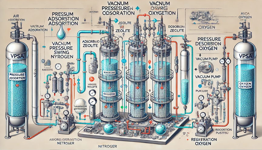
Vacuum Pressure Swing Adsorption (VPSA) is an advanced technology for separating oxygen from air. It utilizes the difference in adsorption capacity of various air components on adsorbents. The adsorbent selectively adsorbs gases when pressure is increased and desorbs to regenerate when pressure is reduced to a vacuum state.
VPSA oxygen generation equipment operates using electricity as the power source and air as the raw material. It leverages the property of molecular sieves to increase the adsorption capacity of nitrogen under positive pressure and decrease it under negative pressure. A cyclic process of positive-pressure adsorption and vacuum desorption is achieved by alternating the operation of the 2 adsorption vessels, enabling the separation of oxygen and nitrogen from the air and the continuous production of industrial oxygen.
The VPSA oxygen generation process is a physical adsorption process, involving no chemical reactions or environmental pollution, making it an ideal oxygen supply method. Compared to traditional cryogenic oxygen production, the VPSA process offers significant advantages, including simpler composition and process, easier operation, more rapid startup, safe and reliable normal-temperature and low-pressure operation, lower energy consumption, and significantly lower oxygen production costs.
1.1 Two-Vessel VPSA Oxygen Generation Equipment Process
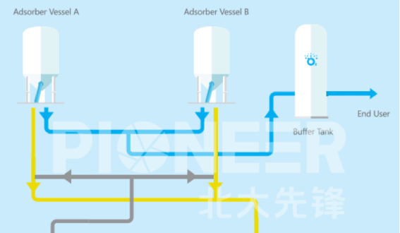
VPSA oxygen generation equipment uses air as the raw material. The air first passes through an air filter and enters a Roots blower, where it is compressed before entering an adsorber that has completed regeneration and is in operation.
Inside the adsorber, moisture, carbon dioxide, and other molecular gases in the air are preferentially adsorbed. The dried air then passes through a specialized molecular sieve for oxygen production, where nitrogen is adsorbed, allowing oxygen to be enriched at the outlet. The oxygen-rich gas is then pressure-regulated through a control valve and enters a buffer tank. At the buffer tank outlet, the oxygen is further compressed by an oxygen compressor to reach the required pressure. The high-pressure oxygen is then cooled and stored in an oxygen storage tank, from where it is supplied to the end users.
To ensure a continuous and stable oxygen supply, VPSA oxygen generation plant is designed with two adsorption towers that operate alternately. While one tower produces oxygen, the other is undergoing vacuum regeneration. During regeneration, the adsorbed rich nitrogen is desorbed and discharged outdoors after noise reduction treatment.
1.2 Application Scenario
The VPSA oxygen equipment is suitable for industrial oxygen production of various scales, providing oxygen with a purity of approximately 80%–93%.
2. Basic Components of VPSA Oxygen Plant
VPSA oxygen unit consists of 7 major components, including radial adsorber system, power system (blowers and vacuum pumps), instrumentation and electrical system, oxygen buffer tanks, oxygen compression system (optional), electrical control system, and water system.

The VPSA Oxygen Generation Process FlowDiagram
2.1 Radial Adsorber System
The oxygen-nitrogen separation unit is the core component of the oxygen generation equipment. It primarily consists of 2 alternating adsorption towers, along with pneumatic switching butterfly valves, pneumatic regulating butterfly valves, and manual butterfly valves. The separation of oxygen and nitrogen is achieved based on the difference in the adsorption capacity of nitrogen and oxygen molecules on high-efficiency, specialized oxygen molecular sieves during the positive-pressure adsorption and negative-pressure desorption processes.
A programmable logic controller (PLC) controls the solenoid valves, which in turn regulate the pneumatic valves according to a set sequence. This enables the automatic operation of the oxygen system, thus ensuring continuous oxygen production. Meanwhile, the vacuum pump evacuates and discharges nitrogen and other gas components.
2.1.1 Adsorption Vessel
The dual-adsorber structure ensures a continuous gas supply to meet customer demands. Inside the adsorber, dehydration molecular sieves and LiX molecular sieves are filled to effectively separate air components and meet oxygen production requirements.
2.1.2 Pneumatic Switching Butterfly Valve
The solenoid valves are controlled by the control system to periodically switch the gas flow between the two adsorbers, ensuring stable operation of the oxygen equipment.
2.1.3 Pneumatic Regulating Butterfly Valve
During the pressure equalization and purging process, a pneumatic control butterfly valve is installed to optimize the equalization and purging effects. The valve features equal-percentage adjustability, zero leakage, and long service life, etc.
2.2 Power System – Blower
As the air intake power component of the entire system, the blower provides a suitable positive-pressure gas source for the oxygen-nitrogen separation system, playing a critical role in ensuring the stable and efficient operation of the system. The blower system includes an inlet air filter, the blower and its matching motor, a bypass pneumatic switching butterfly valve, a manual butterfly valve, a heat exchanger, bellows connectors (or flexible joints), and other supporting complete sets of equipment.
2.2.1 Blower Unit and Matching Motor
The Roots blower is a positive displacement gas blower. Inside its housing, two impellers maintain a specific meshing gap and are driven by synchronous gears to rotate at equal speeds in opposite directions. This mechanism pushes the inhaled gas from the inlet to the outlet, overcoming the resistance of the high-pressure gas on the outlet side to achieve forced exhaust.
Within the housing, two figure-eight-shaped rotors are installed perpendicularly on a pair of parallel shafts. The rotors are driven by a pair of gears with a 1:1 transmission ratio to rotate synchronously in opposite directions. A certain gap is maintained between the rotors and between the rotors and the inner wall of the pump housing.
The key component of a Roots blower is the rotor, and the core of the rotor lies in its profile. The impellers adopt a newly designed special profile, ensuring uniform meshing clearance between the two rotors, reducing internal leakage, and improving volumetric efficiency. Additionally, high-precision and high-performance components such as synchronous gears, bearings, and PTFE seals ensure stable operation with low vibration.
The matched motor is a three-phase asynchronous motor with a protection rating of IP23–IP54 and an insulation class of F. It features high efficiency, energy savings, low noise, minimal vibration, lightweight design, reliable performance, and easy installation and maintenance.
2.2.2 Bypass Pneumatic Switching Butterfly Valve & Manual Butterfly Valve
To improve the recovery rate of product gas during the VPSA and PSA process, the 2 adsorbers undergo an equalization process for a certain period. During this equalization phase, the blower bypasses and vents excess gas. Additionally, to prevent backflow when the blower stops, a bypass depressurization protection mechanism is required. Therefore, a bypass system is installed, where the pneumatic switching butterfly valve is program-controlled to discharge externally. Furthermore, a manual butterfly valve is set up to effectively regulate the blower’s outlet pressure.
The valve is a double-offset hard-seal pneumatic butterfly valve, designed for short-cycle frequent switching. It features zero leakage, long service life, and short switching time.
2.2.3 Heat Exchanger
After pressurization by the blower, the outlet air temperature reaches approximately 65°C, while the optimal working condition for the molecular sieve is between 30–40°C. To ensure the efficient utilization of the molecular sieve, a heat exchanger is required to cool the heated air.
2.2.4 Bellows Connector
During the operation of the Roots blower, significant vibration is inevitable. To minimize the impact of vibration on subsequent equipment and reduce noise caused by vibration, paired flexible connectors and bellows connectors are installed at the blower's inlet and outlet.
2.3 Power System – Vacuum Pump
Once the molecular sieve reaches dynamic saturation during adsorption, the desorption and regeneration is necessary. Studies have shown that molecular sieve regeneration is more effective under negative pressure (vacuum) conditions. The vacuum pump system is an indispensable component of the entire system. It consists of the vacuum pump unit and its matching motor, a bypass pneumatic switching butterfly valve, a manual butterfly valve, bellows connectors (or flexible connectors), and other auxiliary equipment.
2.3.1 Vacuum Pump Unit & Motor
The Roots vacuum pump is a rotary volumetric vacuum pump, structurally derived from the Roots blower. Its working principle is identical to that of the Roots blower.
2.3.2 Bypass Pneumatic Switching Butterfly Valve & Manual Butterfly Valve
To prevent backflow when the vacuum pump is shut down, a bypass is installed to release pressure in advance, ensuring zero-pressure startup and shutdown. A bypass valve is installed for this purpose. Additionally, a manual butterfly valve is used for fine adjustments of the vacuum pump’s suction pressure.
The valve is a soft-sealed switching butterfly valve, designed to meet zero-leakage requirements under long-term switching conditions.
2.3.3 Bellows Connector
During the operation of the Roots vacuum pump, significant vibration is inevitable. To minimize the impact of vibration on subsequent equipment and reduce noise caused by vibration, flexible connectors or bellows connectors are installed at the vacuum pump's inlet and outlet.
2.4 Instrument Air System
Both the pneumatic butterfly valves and pneumatic regulating butterfly valves require an instrument air source of approximately 0.5-0.7 MPa as the actuator’s driving force during automatic control switching. The system consists of components such as an air source treatment filter and an air storage tank. To ensure the operation rate, a bypass valve is added to the filtration unit which requires frequent maintenance and servicing.
2.5 Oxygen Buffer Tank
The oxygen buffer tank system mainly consists of an oxygen buffer tank, orifice flowmeter, oxygen purity analyzer, control valve, and pressure sensor.
The oxygen buffer tank serves as a key measure to mitigate excessive pressure fluctuations in the adsorbers and to stabilize the pressure and purity of the product oxygen.
2.6 Oxygen Compression System (Optional)
The oxygen compression system consists of an oxygen-specific butterfly valve, an oxygen compressor, and other components. Its primary function is to increase the pressure of the product oxygen to meet the user's required pressure and deliver it to the oxygen storage tank.
The oxygen storage tank system includes oxygen storage tanks, valves, pressure gauges, safety valves, and other components. Its main function is to store a portion of the product oxygen, ensuring stable oxygen output. Additionally, it provides a temporary oxygen supply in the event of an unexpected shutdown, preventing the oxygen supply system from failing.
2.7 Electrical and Instrumentation Control System
The electrical and instrumentation control system includes an industrial computer, electrical control cabinet, instrumentation cabinet, programmable logic controller (PLC), solenoid valves, indicator lights, control buttons, and other components.
The system operates automatically according to the program edited in the PLC, controlling the energization and de-energization of the solenoid valves, which in turn open and close pneumatic valves via the pneumatic control system. It collects and processes various signals, displaying the operating status of the oxygen equipment. Users can set or modify control parameters on the industrial computer to configure or check the equipment's operating status.
2.8 Water System
The water system typically consists of two parts: the circulating water system and the sealing water system. The circulating water system mainly includes a cooling tower, water pumps, filters, inlet and return water pipelines, and associated valves. It provides cooling circulating water for the entire oxygen system. The sealing water system is primarily used to supply water to the vacuum pump impeller to enhance sealing, thereby achieving a higher vacuum level during the desorption process. Soft water or desalinated water, whose production system is provided by specialized manufacturers, is typically used for this purpose.
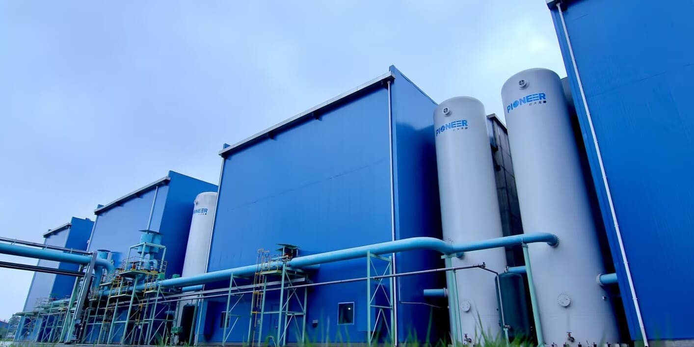
PKU Pioneer's VPSA and PSA oxygen generation technology stands out as a cost-effective, flexible and reliable solution for industrial oxygen supply. With an oxygen flow range of 50~100,000 Nm3/h and general purity levels of 80~94%, our oxygen systems offer significantly lower cost advantages over traditional ASU (Air Separation Units) or LOX (Liquid Oxygen) methods. The self-produced lithium-based adsorbent and innovative radial-tower process design ensure larger oxygen capacity, optimal performance and energy efficiency. Over the past 25 years, we have successfully implemented over 400 oxygen plant projects worldwide, including the world’s largest VPSA-O2 system project (146,000 Nm3/h) and China’s largest VPSA-O2 plant (87,500 Nm3/h).
PKU Pioneer has exported VPSA/PSA systems to over 20 countries and regions, serving 30+ industries with proven expertise. Our CE-certified containerized SPOX VPSA-O2 generator has been exported to Italy and the PSA-CO plant will be built in the US. With the most VPSA and PSA references worldwide, PKU Pioneer will continue to lead the industry in providing efficient, sustainable, and customized oxygen solutions to meet the unique needs of more clients.
About the Author
Founded in 1999, PKU Pioneer specializes in VPSA and PSA gas separation technologies, adsorbents, catalysts, and integrated engineering solutions. Backed by strong R&D capability and extensive industrial project experience, the company serves global customers across steel, chemical, energy, environmental protection, and related industries.
Share
Related News
-
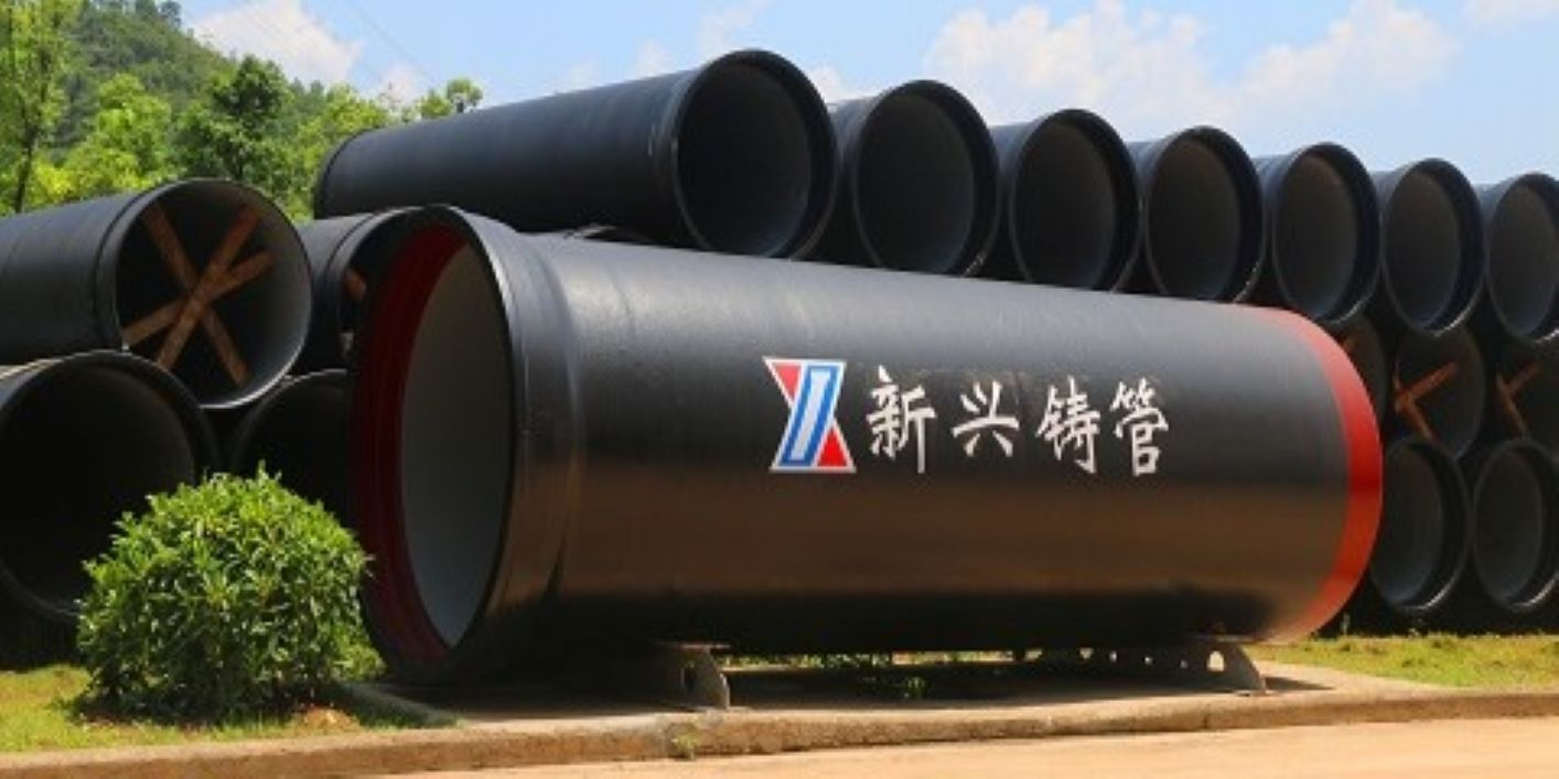
PKU Pioneer Project Spotlight: VPSA Oxygen Generation Project for Xinxing Pipes Now In Operation, Generating Over $1.76 million Annual Revenue
PKU Pioneer’s VPSA oxygen generation project for Xinxing Pipes now operates successfully, supplying 6,000 Nm3/h of oxygen for blast furnace enrichment. The system cuts costs, eliminates liquid oxygen reliability, and generates over $1.76 million annual revenue, with expected investment payback within three years. -
Breakthrough! PKU Pioneer’s First VPSA Oxygen Plant Landing in Vietnam
In March 2026, PKU Pioneer built collaboration with our first Vietnamese client for a 10,000 Nm³/h VPSA oxygen system. With 25+ years of expertise and over 100 global steel clients, the company ensures rapid deployment, under 0.3 kWh/Nm³ power use, and $3-8 million annual savings. -
Process Flow and Technical Principles of PKU Pioneer 25,000 Nm3/h Oxygen Generation Equipment
Ⅰ. Equipment Description Basic principle of pressure swing adsorption (PSA) oxygen production: Raw air is filtered to remove impurities through the blower inlet filter before entering the blower. After being pressurized by the blower, it enters the adsorbent bed via pipelines and pneumatic switching valves. Moisture and carbon dioxide in the raw air are adsorbed…